Current plan
M-01 running
- Energy over 30 min
- 31.1 kWh
- Peak power
- 64.7 kW
Hardware / Industrial 4G LTE Router
A gateway for control cabinets, PLCs and meters, with Ethernet, RS485, 4G LTE and Node-RED.
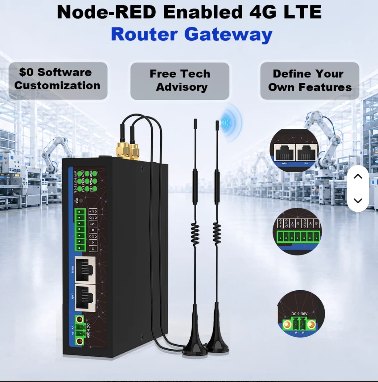
Industrial 4G LTE Router
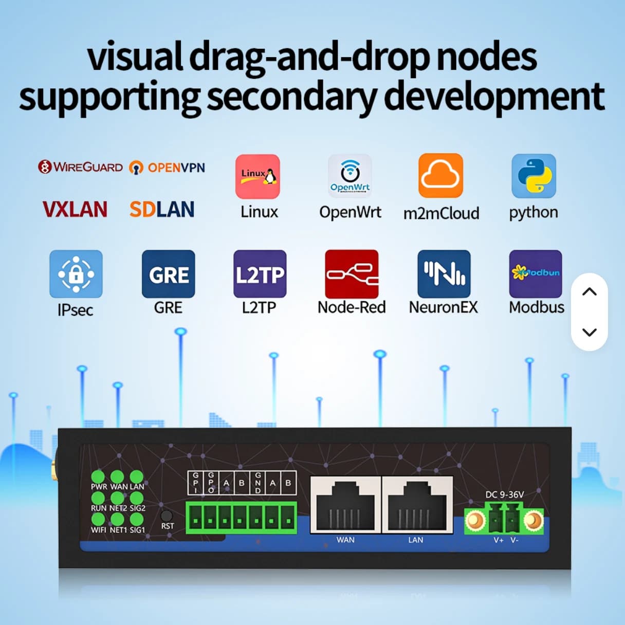
Details are based on supplier reference images. Confirm the model, specifications, included accessories and AIoT TH Cloud integration before quotation.
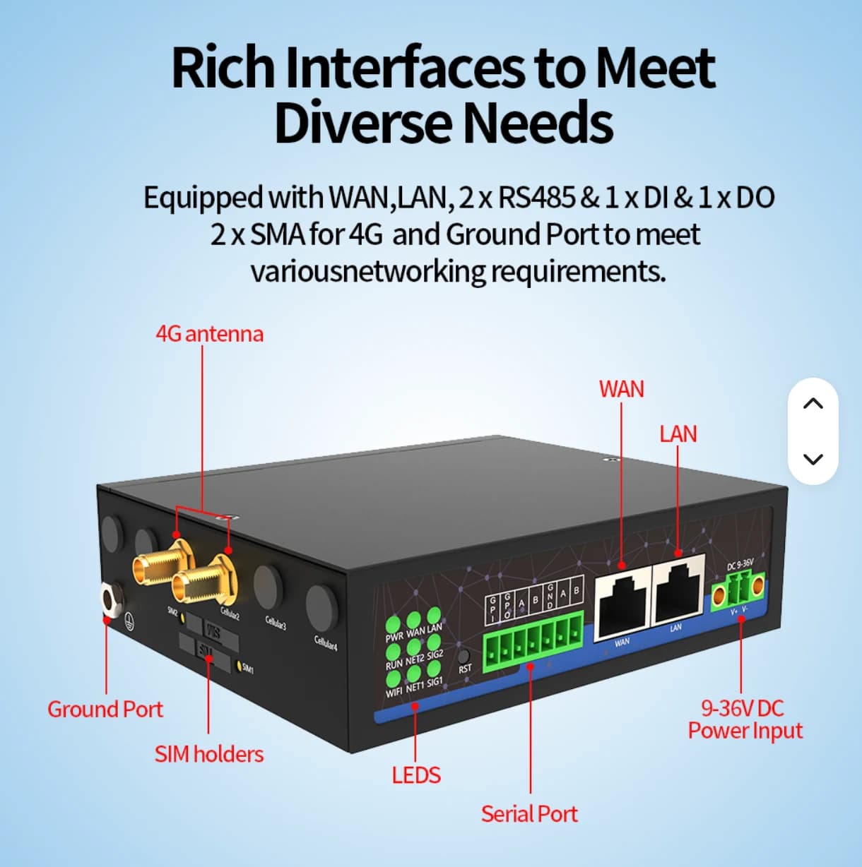
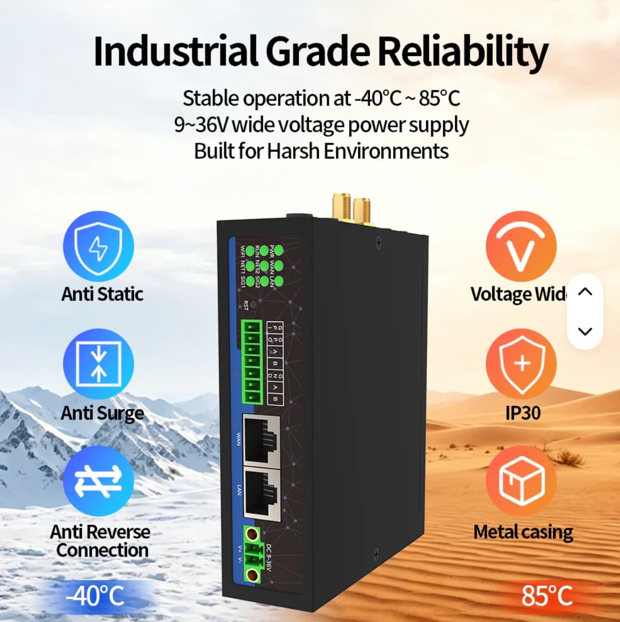
For factories, electrical cabinets and wired measurement points.
Have the site owner confirm power, installation position and networking before selecting accessories.
DO is a hardware capability. AIoT TH Phase 1 reads data; device control and optional software require a separate project scope.
FACTORY APPLICATIONS
Illustrative system designs with equipment, data, responsible teams and project conditions. These are not customer case studies.
DIGITAL TWIN · SIMULATED
This simulated digital twin is a model running in your browser. It does not mirror a PLC or customer site and does not control equipment.
Live (simulated) · 08:00:00
Illustrative 3D layout, not surveyed coordinates. Scene labels show values from the simulated twin. Select equipment on the scene or in the twin tree.
WHAT-IF · SIMULATED
M-01 running
M-01 stopped
Computed from the browser simulation to compare choices; not a prediction for a real site.
Select a scene device, then inspect or control it
PLC / Meter → Modbus TCP / RS485 → Gateway → MQTT TLS :8883 → Monitor
CCTV uses IP over PoE / NVR independently of LoRaWAN. This scene is illustrative and has no live video.
Connect power readings and machine states to site locations for maintenance inspection.
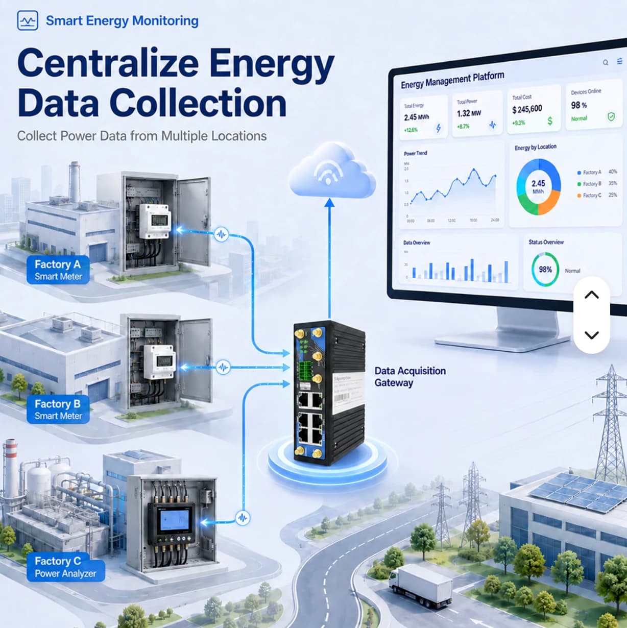
Move from a monthly total to area-level meter readings that engineering teams can use to investigate loads and plan improvements.
Suppose a factory wants to monitor three metering points. Start with readings and history for each point. Cost calculations or energy per unit require additional data and agreed formulas; they are not automatically included.
Teams investigate several cabinets and may act on the wrong source
Approach · Define main and submeter boundaries, collect readings by point and compare periods with similar production conditions
Differences may reflect timing rather than actual load changes
Approach · Read supported meters through a gateway, standardize names, units and timestamps, and compare values with the meter display
The team lacks event-time data to prioritize equipment checks
Approach · Agree site-specific thresholds, enable scoped notifications and assign a person to investigate the equipment
Electrical engineer
Select comparison points and identify main versus submeter boundaries to avoid double counting
Equipment owner
Verify registers, units, CT ratios and polling intervals for the actual meter
Installer and site team
Compare the dashboard with the meter at matching times and record discrepancies
Energy engineer
Read current values and history alongside operating schedules, not totals alone
Maintenance
Check equipment and production conditions before deciding on an operational change
Production manager
Compare similar operating periods and record changes and remaining data gaps
Identify periods and areas that merit further load investigation
Use timestamped readings when checking notified equipment
Review machine-start schedules and shift changes with supporting data
Support improvement proposals with measurements; cost formulas still require separate validation
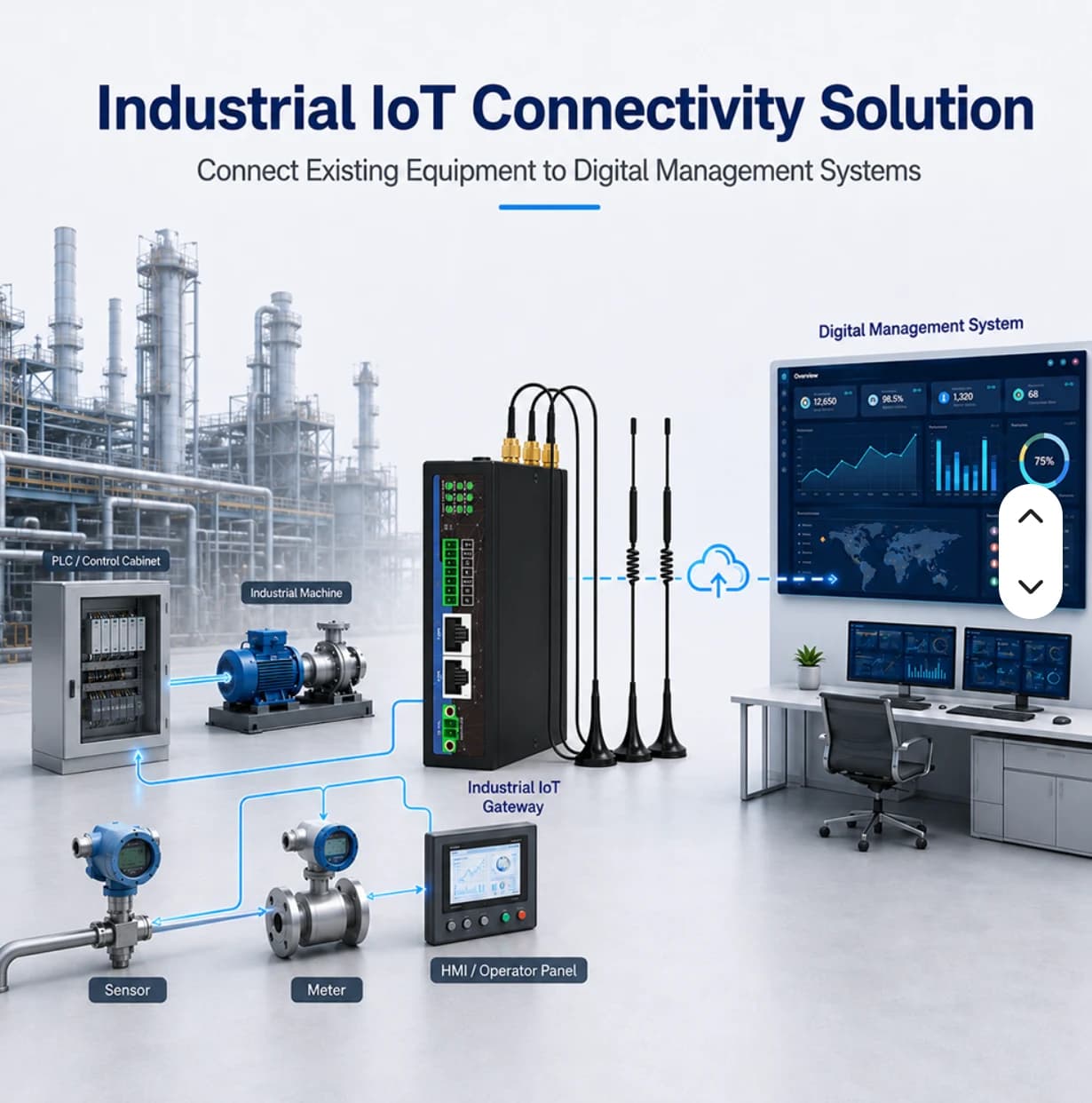
Connect PLC or sensor signals so production and maintenance use the same observations before developing performance analytics.
This illustrative line has feeding, filling and packing stations. Start with run/fault states and counters exposed by the PLC. Existing controls are not automatically modified, and an offline gateway is not treated as evidence of a machine stop.
Shift leaders lack a shared view across multiple machines
Approach · Define readable PLC states and display them by machine with update timestamps
Investigations begin without reliable times and source signals
Approach · Retain relevant states and readings to identify investigation periods; a person still confirms the actual cause
A calculated number may not represent production correctly
Approach · Separate acquisition from analytics and define shifts, counts, good units and ideal cycle times before agreeing OEE formulas
Production and PLC owner
Agree run, stop and fault meanings, including changeovers and planned stops
Automation engineer
Document addresses, types, units and a read method that does not interfere with control
Installer and operator
Compare displayed states with machine behavior during an agreed test
Shift leader
Check states and freshness, using history to select periods for investigation
Maintenance
Inspect the machine and record causes through the factory process rather than assuming them from one signal
Production engineering
Validate counts, shifts and formulas before adding downtime or OEE analysis
Coordinate using station-level readings and event timestamps
Use historical signals as evidence rather than relying only on recollection
Maintain and extend the system using shared point definitions
Identify available and missing inputs before investing in performance analytics
DETAILS & PLANNING
RS485 defines an electrical interface, not universal protocol compatibility. For Modbus RTU, verify baud rate, parity, stop bits and slave IDs against the correct register map. Port count alone does not establish practical device capacity without reviewing the bus and polling configuration.
The reference images advertise Node-RED and Python customization. Confirm the firmware, resources and packages of the delivered variant, plus who maintains the flows or code. Adding gateway logic does not authorize PLC control without a separate design.
Review each system’s scope before opening it or using the example to plan your project.
Simulated data · No physical PLC commands
Explore machine states, energy, simulated readings and alarms with a 3D scene and example event history.
Live public observations · Read-only
View rain, water-level and road-water observations on a station map with timestamps and source attribution.
The images are supplier references. Confirm the delivered variant, firmware and network requirements before specifying VPN capabilities for a project.
No. DO is a hardware capability; Phase 1 of the platform focuses on reading data. Control requires a separately agreed design.
Start with your equipment and data points, then define the right site scope.